Are you planning on building a stereo tube amp, but don’t know where to start and how to move forward? If so, then you’ve definitely landed in the right place.
Building a stereo amp from scratch will involve understanding the basics of stereo tube amps, gathering the necessary components, planning the layout, adding the power supply and audio circuit, and finishing up before testing. It might sound complex, but it’s actually a simple process if you know the right steps.
In this article, you’ll get to know all about stereo tube amps, safety precautions to remember for how to build a stereo tube amp, and a step-by-step guide on how to build a stereo tube amp from scratch. Continue reading to get all the answers that you’re looking for.
Safety precautions for how to build a stereo tube amp
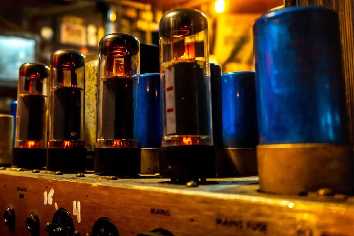
Have you ever wanted to build a dangerous, inefficient, yet amazing retro piece of electronics? This is essentially what a vacuum tube amplifier is. Vacuum tubes are old electronic components that’ll like transistors and control a lot of current with a bit of current. You’re usually hearing about tubes used in guitar amps, as they distort in a way that perfectly suits guitar playing.
However, tubes can be used for amplifying a stereo signal from another audio source, like a CD or MP3 player. Tube amps, unfortunately, aren’t really the most practical things in the world. These consume a huge deal of power, are huge, and get very hot. With that said, they will look very cool, and some people may think that they sound nice too.
>>> Click here to read our review about the Top 15 Best Tube Amps <<<
This project is exceedingly dangerous in a serious way. The process involves high voltages and a great deal of current that can give fatal injuries or even death. If you decide to work on the tube with the power on, you should be cautious. The capacitors are capable of holding on to the charge for a long time even after the power is switched off. You should discharge the capacitors through the resistor connected to ground, preferably using a voltmeter across it to be sure that the cap has discharged completely.
When testing out the amp for the first time, use something like a 12V power brick instead of plugging directly into the wall. This helps you be safe while also preventing things from melting or exploding. An old trick would be to keep your left and in your pocket all the time. This way, even if you get shocked, it won’t reach your heart.
Step-by-step guide on how to build a stereo tube amp from scratch
Step 1: A brief intro to tubes
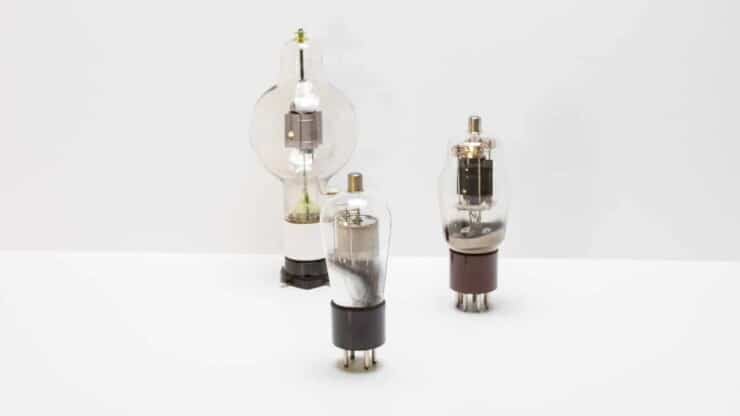
A project like this can teach you a lot about electronics and electricity. To fully appreciate what goes in your amp, you’ll need to have a look at how tube amps work. First up would be the vacuum tubes themselves.
A vacuum tube is essentially just a glass that has all the air sucked out of it. A decent example will be the early lightbulb, inside which the filament will be subjected to a current. This caused it to produce energy in the form of heat and light. Say that the interior of the bulb wasn’t a vacuum. Then, the filament would have combusted because of high temperature in the presence of oxygen and gotten destroyed.
Diodes
The most basic type of vacuum tube is a diode. It is named this way due to the two electrodes that it contains. Vacuum tubes are thermionic, which means that the heat is used for the emission of electrons from the electrode. If a negatively charged electrode is heated by a filament, the electrons present will become “excited”. If a sufficient voltage or electric potential difference is present, they’ll actually get emitted through the electrode.
The potential difference will be because of another electrode called the plate or anode. This is positively charged and will exert an attractive force on the enthusiastic little particles. It causes them to travel across the vacuum from the cathode, which is negatively charged. As electric current flows from negative to positive, the current will only flow one way in the diode.
Triodes
In triodes, there’s a third electrode apart from the anode and cathode, called the “grid”. The grid will carry a negative voltage and will be connected to an input source. In the case of tube amps, there’s a fluctuating audio signal. The negative voltage on the grid will repel a certain amount of electrons leaping off of the cathode. How many electrons it’s repelling will depend on how negative it is and the amplitude of the audio signal. This is essentially the definition of amplification – using a small amount of electricity for controlling a large amount. The audio signal will be small.
Moreover, it will effectively control the flow of the electrons you want to saturate the cathode with. The base voltage of the grid and the voltage present will be referred to as the bias voltage. The bias will determine how much current the tube is drawing when there’s no input signal.
Step 2: The parts you’ll need
The stereo tube amp will be made up of two sections, the power supply, and the audio circuit. It’s important to have a look at both parts.
Enclosure
You’ll need something to put your tube amp in, and there are certain considerations to keep in mind when picking an enclosure. Transformers and the tubes themselves can get quite hot, and you’ll need to be in a well-ventilated area. It should preferably be jutting out of the top of the case.
You shouldn’t go for an enclosure purely based on its looks. Otherwise, you’ll end up with a headache. Beginners sometimes go for old wooden cutlery cases, which have thick panels and make it painful to mount components. Instead of choosing aesthetically good-looking enclosures, you should go for something a bit more conventional.
Transformers
You will have to make the audio circuit twice as it is a stereo amp. To achieve that, you’ll be requiring two output transformers. Instead of going for fancy special order transformers that might be out of your price range, you can go for options that fit your budget. Settling for something like the Hammond 125D will be a good alternative plan.
There are four transformers in the power supply. The first one will be the heating filaments in the tubes (Hammond 166N6). The second one will be for the main positive supplies (Hammond 167G120). The third one will be for negative supplies (Amveco toroid) and lastly a choke transformer (Hammond 158Q). The choke isn’t actually a transformer, but it is an inductor. The function of the choke is very similar to that of the capacitors in parallel. It’ll resist sudden changes in current, and it’ll act as a filter.
Tubes
The tetrodes used in the main amp section will be four Electro-Harmonix 6V6EH tubes, and they’re very easy to find. For the preamp tubes, you’ll be using 5965 tubes, which are double triodes. This means that each tube actually features two triodes. If you explore the guts of the tube, you’ll notice two separate metal sheaths that are actually triodes. Tube sockets will be important for affixing the tubes to the case.
Resistors
You can use regular metal film resistors, although you can also include a few high-quality Kiwame resistors in there. The 60W and 62.5 4W resistors that you’re seeing in the schematic called the plate resistors will actually be two 2W each in parallel, a couple of 120K’s for the 60K and 120K and 130K for the 62.5K.
There are some nice resistors that are pretty cheap, but most guitarists prefer using high-quality ones for the plate load. However, these aren’t necessary for every situation. The 100-ohm resistors connected to the 6V6 screen will be rated at a 1/2W and complemented with regular old resistors. The same will apply for the 100K bias resistors and metal film.
Capacitors
The two 0.33uF capacitors are meant to cut off any DC coming through, and they’ll allow just the AC audio signal to pass. While expensive capacitors are pretty nice here, but you can still go for cheap capacitors, and they’ll do just fine. Say that the ones in your amp are 0.47uF, but it means that you’ll be getting a bit more bass. All the capacitors in the power supply can be standard components, you can also add a few orange drop-style caps.
Diodes
You can use the UF1007 1000V 1A diodes as it is recommended by plenty of technicians. You won’t necessarily need anything expensive, unless you’re choosing to use tube diodes. Tube diodes will likely cost you extra and need a power supply for their heaters.
Potentiometers, jacks, and switches
There will only be three potentiometers in the amp. There’s one for volume and the other two for adjusting the bias on either channel. The one for volume is known as a double-deck pot.
There will be two switches, one for the tube heaters and the other for the main power supplies. The regular, old single-pole double-throw switches will be just fine here. If you have a single input in your amp, you won’t need a DPDT for changing between inputs. You’ll also require two sets of speaker winding posts. This way, you’re having something to hook the speakers up to and as a plug for the power cord, and as a set of stereo input jacks.
Step 3: What goes on in the audio circuit
The basic principle behind this stereo tube amp is pretty cool and is known as the push-pull principle. This amp is a 6V6 Push-Pull amp, and the 6V6 is the tube mode. Push-pull refers to a special case of differential circuits where the whole signal will be made up of the difference of two voltages, a positive and a negative.
Technically, only the output stage will be push-pull, but both of them are differential. Simply, one tube will produce the positive side of the AC audio signal and pushes the speaker out. Meanwhile, the other one will produce the negative half, pull the speaker cone in, and create sound waves.
For instance, take the two triodes in the preamp. The cathodes will be connected, and the signal will go to the grid of one of the tubes. When the signal goes high, the grid on one of the tubes repels fewer electrons jumping off the cathode. As the cathodes are connected, the electrons rush out to the cathode of the other tube too.
This will result in the current flowing in a particular direction through the circuit and through the transformer. This produces the current and forces the speaker cone to move outwards. Once the signal goes low, the opposite will occur. The grid will repel the electrons back to the cathode, and the electrons will go to the cathode of the other tube. This will send the current in the opposite direction as before. When the current goes through the output transformer’s primary coil, it’ll induce a current in the secondary coil. This will cause the speaker cone to move inwards.
Before it’ll go to the speakers, the signal will get filtered through the two 0.33uF capacitors and make its way onto the output stage or to the main amplifier section. Then, everything will happen all over again, except this time it’ll be with the 6V6s and to a greater extent. The -20 DC voltage in the middle is for the bias on the grids of the 6V6s. The shield of the 6V6s will be connected through a resistor to the anode, which means it has a fraction of the anode voltage.
Step 4: Layout and planning
This is arguably the most important part of the entire project. It’s important to put everything in the right place to start off, as it’ll make the experience smoother. You shouldn’t always go for the most pristine option, instead, go for any decent option that works.
You’ll also want to keep the audio circuit and the power supply as two separate sections/sides. All the tubes will go together in one area and the output transformers will be somewhere nearby. By putting the transformers too close, it can end up causing a hum. Some hum issues can be easily solved by putting the metal covers over the transformers and grounding the cases properly. In the amp, the bolts that fix the transformers to the case will be firmly attached to the ground plate via nuts.
The positioning of transformers relative to one another will also help in eliminating hum. By rotating the transformers 90° so that they’re not in line with each other, you’ll get a decrease in hum. Moreover, the angle isn’t always 90°. If you’re picky and patient, carefully adjust the angle until it is an optimum option.
Step 5: Deciding upon the enclosure
For your DIY stereo tube amp, you can pick an old cutlery box as the enclosure. This type of case is wonderful, but it isn’t always recommended as it can be quite a hassle. The tops and sides are pretty thick, which makes it difficult to mount components that are meant for plastic cases or thin metal cases without grinding away at the thing.
A metal enclosure things much easier to ground things. In such cases, you can connect the ground to the chassis and ground anything in the circuit by easily connecting it to the chassis. With the cutlery box, you can put copper-coated plates for solving the problem. If you’re looking for a cool-looking wood enclosure and are fine with the extra work, you should go for it.
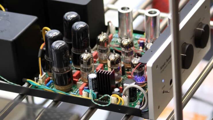
Step 6: Getting started with the build
You can put the audio circuit on one side and the power supply on another. On the inside of the case, attach a copper-coated plate, as it’ll serve to ground anything connected to it. This will make it very easy to ground the exteriors of the transformers and reduce the hum. The transformers will be firmly connected to the plate with nuts and bolts, which fixes the plate to the inside of the case.
Step 7: Building the power supply
As long as you know the basics of soldering, you will not have a lot of trouble putting everything together. If you don’t, it would be a smart idea to do it under the supervision of an expert. There will be two copper plates present, one for the audio circuit and the other for the power supply. While this is a decent route, having one big plate covering the entire surface will be even better.
Ultimately, you’ll have to figure out from experience and experimenting what should be the layout for the amp. Either yourself or with the help of an expert, figure out where you should put the tubes and how you can bridge the gap between the power supply and the audio circuit.
In some sections, there will be some sort of free-form circuitry as well. There will be little clumps of components that get soldered directly to one another. This will be a bit more confusing than using a PCB, which will be quiet and save you the trouble of worrying about creating space for and designing the circuit board. The terminal strips will keep most of them anchored tightly and securely to the case.
Step 8: Building the audio circuit
The entire process of making the audio circuit may feel a bit messy and complex. You will be soldering the components to the legs of the sockets, there will be wires crisscrossing, and more. If you’re doing this for the first time, you shouldn’t be chasing perfection. Once you become more and more experienced, you can go back to it again and improve.
The red capacitors will be 0.33uF, but you can also use 0.47uF, as it won’t be a big issue. It simply means that you’ll b able to get a bit more bass. Moreover, they’ll be able to hold on to a big charge and be extra careful with them and make sure you discharge them. These components are probably worth replacing with high-quality parts in the future. However, most people will agree that they’re important to the sound of the amp. Don’t forget, you’ll be building the audio circuit twice, since this is a stereo amp.
Step 9: Finishing and testing the stereo tube amp
Once you have put everything together, it’ll be time to see if your new stereo tube amp is actually working. However, you shouldn’t plug it directly into the wall right off the bat. If you do this, and you had made any wiring mistakes, you could easily end up frying the internal components. If smoke comes out of it, this is probably not a good sign. You can use a power adapter for a smartphone or some other low-ish voltage device for checking everything first.
Connect it to the power socket’s terminals and use a multimeter for testing the points of voltage. With a power adapter, the voltages might be off by a factor of ten or so. In case everything looks right, you should go ahead of plug and hopefully, nothing will burst into flame. Once the power supply starts behaving, hook up the speakers and see how it is sounding.
Conclusion
Hopefully, now you know a lot more about stereo tube amps, safety precautions to remember for how to build a stereo tube amp, and a step-by-step guide on how to build a stereo tube amp from scratch. Building a DIY stereo tube amp from scratch is easy once you know the right steps. It’ll involve understanding the basics of stereo tube amps, gathering the appropriate tools and components, planning the proper layout, adding the audio circuit and power supply, and testing the finished tube amp. Another key tip to remember would be to prioritize and follow all the necessary safety protocols.

